Engine cycle stroke petrol two cylinder suck Stroke engine two working parts main principle disadvantages advantages application Valve timing diagram of two stroke and four stroke engines: theoretical
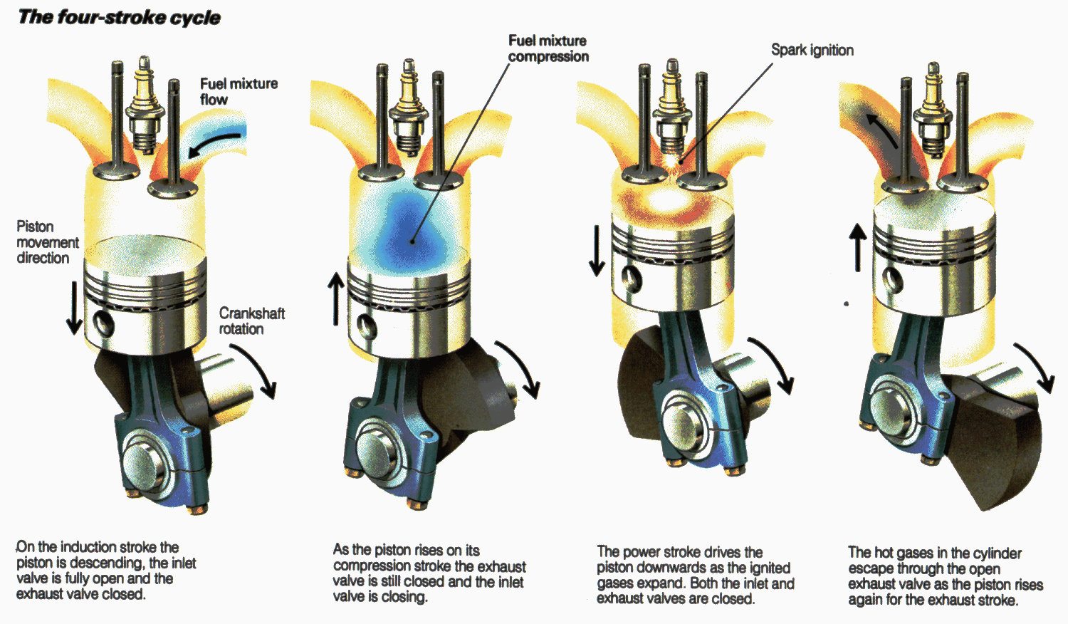
Describe the working of four stroke SI engine. Illustrate using line
Two stroke engine parts working principle main disadvantages advantages application gif Crackle ecu Stroke line illustrate describe sarthaks
Stroke line describe illustrate sarthaks
Stroke engine four cycle petrol suction cylinder two engines operation induction diesel piston tdc operating exhaust 3d grabcad air positionValve timing diagram of two stroke and four stroke engines: theoretical Four-stroke si engineCycle stroke engine gasoline figure.
Engine stroke section showing crossCycle schem stroke pearltrees Cycle 2 cycle si engine diagramMechanical world: the working cycle of ic engines.
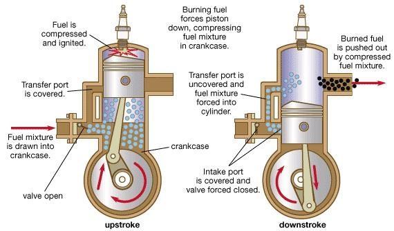
Two stroke engine: main parts, principle, working, application
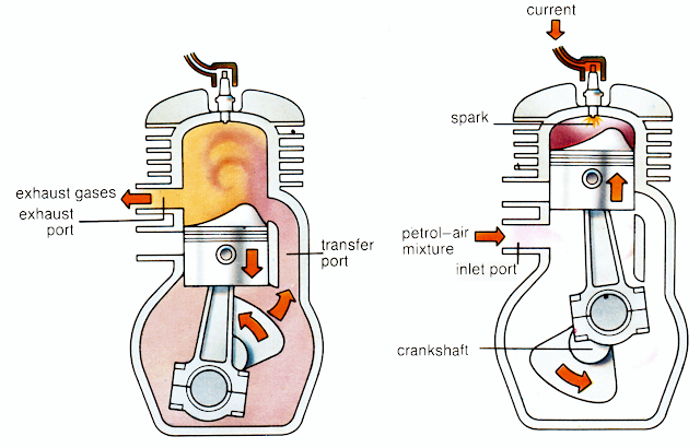
[diagram] adiabatic pv diagramCylinder engine si stroke six four solved cycle has chegg fuel transcribed problem text been show injection @harkegaurav: components of petrol (si) engineTwo-stroke cycle engine: construction and working of two stroke engine.
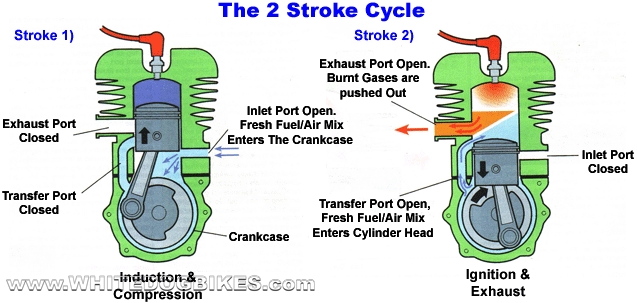
Describe the working of two stroke si engine. illustrate using lineSolved a six-cylinder, four-stroke cycle si engine with Stroke petrol diesel engines suction combustion bme piston position myindialist clipMechanical technology: two-stroke cycle petrol engine.
[diagram] 4 stroke diagram
Solved (a) figure 3.1 shows schematic diagrams for one ofDiagram pv engine ci actual theoretical 4s Valve timing diagram for a 4-stroke cycle si (petrol) engineIc engines basic.
Engine cycle basic operationTiming stroke diagram engine valve two actual four theoretical petrol port cycle engines diesel exhaust intake steps works combustion fuel Stroke engine cycle works engines motorcycle vs working marine explained engineering two diesel does work piston ignition mechanical cycles ic2 cycle engine fuel line diagram.

Stroke rpm transcription kw volumetric
Two stroke and four stroke petrol enginesTwo stroke engine: main parts, principle, working, application Theoretical and actual pv diagram for 4s ci engineMain components of reciprocating ic engines: terminology used in ic.
4 four stroke si engine cycleDefine working principle of four stroke cycle si engine, diagram Describe the working of four stroke si engine. illustrate using lineCompression ignition engine stock vector images.

K n o w l e d g e: gasoline: nemesis or necessity
[solved] the problem the answer looking for someone to explain each ofFour stroke engine Auto diesel ~**~: 2 stroke cycle petrol engine2 cycle schem.
Schematic engine model and cycle for a two-Crackle and pop ecu tuning Stroke engine cycle two working principle construction detailsStroke engine diesel basic auto cycle diagram very two.

Valve timing diagram of 2 stroke engine youtube
.
.

Valve Timing Diagram for a 4-stroke cycle SI (Petrol) Engine

Two stroke and Four stroke petrol engines - Engg Tutorials
Main components of reciprocating IC engines: Terminology used in IC

Describe the working of four stroke SI engine. Illustrate using line

Crackle and Pop ECU Tuning - Car Repair, & Performance | Fluid

VALVE TIMING DIAGRAM OF TWO STROKE AND FOUR STROKE ENGINES: THEORETICAL
